- 您现在的位置:买卖IC网 > Sheet目录371 > 0910CF15B0100E (Johanson Technology Inc)DIR COUPLER W/FILTER 910MHZ
"High Frequency Ceramic Solutions"
910 MHz Directional Coupler/ Low Pass Filter Combination
Detail Specification: 10/13/08
General Specifications
P/N 0910CF15B0100
Page 1 of 4
Part Number
Frequency (MHz)
Attenuation (min.)
Attenuation (min.)
Attenuation (min.)
Attenuation (min.)
Insertion Loss
0910CF15B0100
860 - 960
27 dB @ 2 x Fo
30 dB @ 3 x Fo
30 dB @ 4 x Fo
30 dB @ 5 x Fo
1.2 dB max.
Return Loss
Coupling
Isolation
Impedence
Operating and Storage Temp
Reel Quanity
20 dB min.
10 ± 1 dB
30 dB min.
50 ?
-40 to +85°C
4,000
Terminal Configuration
Packaging
Bulk
Suffix = S
Eg. 0910CF15B0100S
No.
Function
P/N
Style
T&R
Suffix = E
Eg. 0910CF15B0100E
1
Termination
Suffix Termination
Style
100% Tin
Tin / Lead
Suffix = None
Suffix = /Pb
Eg. 0910CF15B0100(E or S)
Eg. 0910CF15B0100(E or S)/Pb
2
3
GND
GND
4
Input
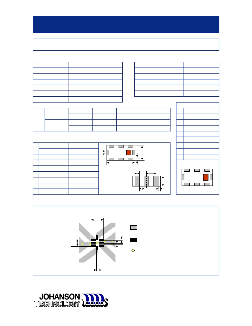
Mechanical Dimensions
5
Coupled Out
In
mm
6
GND
L
W
0.079 ± 0.004
0.049 ± 0.004
2.00 ± 0.10
1.25 ± 0.10
a
c
W
7
8
GND
Output
T
a
0.027 ± 0.004
0.012 ± 0.004
0.70 ± 0.10
0.30 ± 0.10
L
a
p
3
2
1
b
c
0.008 ± 0.004
0.012 +.004/-.008
0.20 ± 0.10
0.30 +0.1/-0.2
T
4
8
g
p
0.014 ± 0.004
0.026 ± 0.002
0.35 ± 0.10
0.65 ± 0.05
g
b
5
6
7
Mounting Considerations
Mount these devices with brown mark facing up.
Line width should be designed to provide 50 ohm impedance, depending on PCB material and thickness
Units: mils
112
Solder Resist
66
14
Land
12
Through-hole ( 12 mil diameter)
14
Johanson Technology, Inc. reserves the right to make design changes without notice.
All sales are subject to Johanson Technology, Inc. terms and conditions.
www.johansontechnology.com
4001 Calle Tecate ? Camarillo, CA 93012 ? TEL 805.389.1166 FAX 805.389.1821
2008 Johanson Technology, Inc. All Rights Reserved
发布紧急采购,3分钟左右您将得到回复。
相关PDF资料
095-1308-09-343
LED BASE T3 1/4 MINI PANEL IND
095-1310-09-303
LED BASE PMI 11/16" SCREW-IN
095-3175-003
CAP MINI PANEL IND WHITE SEALED
0FLR0550X
FLASHER THERM 12V 3TERMINAL HDUT
1003
LAMP INCAND B6 SGL BAYONET 12.8V
1005940-1
SENSOR MINISENSE 100 VERTICAL
101-1293
RCM4510W DEV KIT
101-8430-09-203
LED BASE SUBMINI PANEL INDICATOR
相关代理商/技术参数
0910CF15B0100EPB
制造商:JOHANSON 制造商全称:Johanson Technology Inc. 功能描述:910 MHz Directional Coupler/ Low Pass Filter Combination
0910CF15B0100S
制造商:JOHANSON 制造商全称:Johanson Technology Inc. 功能描述:910 MHz Directional Coupler/ Low Pass Filter Combination
0910CF15B0100SPB
制造商:JOHANSON 制造商全称:Johanson Technology Inc. 功能描述:910 MHz Directional Coupler/ Low Pass Filter Combination
0911 00 13
制造商:LEGRIS 功能描述:Y 1/4BSPT, 1/4BSPP
0911 ANC 101
制造商:Belden Inc 功能描述:0911 ANC 101
0911 ANC 401
制造商:Lumberg Automation 功能描述:Connector, AS-Interface, Branch To Connect Two Flat Cables, 900000243
0911 ANC 406
制造商:Lumberg Automation 功能描述:Connector, AS-Interface, Connects to AS-Interface, 900000213 制造商:Belden Inc 功能描述:0911 ANC 406
0911 ANC 407/2 M
制造商:Belden Inc 功能描述:0911 ANC 407/2 M
